Tutorial: First Light
Goal: energize a single LED, then turn a knob and watch it dim (live, in 3D, on a real routed board). This is the smallest complete slice of what circsim does, and it takes about five minutes.
You'll learn: how to open a board, energize it, read the operating point, add a bench instrument, draw a lead onto the copper, and drive the simulation by turning a knob.
No board file of your own is needed: circsim ships the First Light demo.
1. Open the demo
From the start screen, click Open First Light demo. (Already have a board open? Use Open… in the header and pick a board. The steps are identical.)
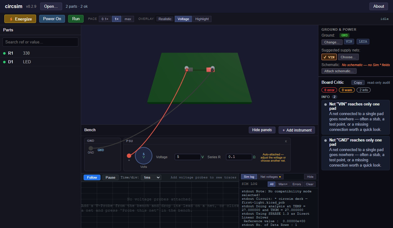
The demo is deliberately tiny: a resistor R1 (330 Ω) in series with an LED D1, across a supply rail. It's the circuit you'd build first on a breadboard, except this one is a routed PCB you can't poke with a jumper wire. That's the point.
The 3D board appears. The Parts panel shows R1 and D1, both with green dots: both fully modeled.
2. Energize
Press ⚡ Energize.
circsim designates the ground net, clips a 5 V supply onto the power rail, and solves the DC operating point. Watch three things happen at once:
- D1 lights up. Not a fake glow: the brightness is driven by the LED's actual forward current (it starts glowing around 0.5 mA and is fully lit by ~15 mA).
- Voltage labels float over each net.
- The copper tints by voltage (the overlay flips to
Voltage).

At 5 V through 330 Ω into a red LED (about 1.9 V of forward voltage dropped when conducting), the current is roughly (5 − 1.9) / 330 ≈ 9.4 mA, a healthy, clearly-lit LED. Hover the parts to read the numbers back.
It didn't glow?
If the LED stays dark, circsim will surface a 💡 coach note in the bottom-left explaining why in plain language: usually a reversed diode or a missing current-limit path. That coaching is a feature: a silent dark LED is a beginner's worst moment, so circsim turns it into a lesson.
3. Meet the supply
Look at the bench shelf below the board. There's already a PSU front panel there: the 5 V supply Energize clipped on for you. It has a Volts knob (currently 5), a numeric Voltage field, and a red + jack with a lead running up to the board's power net.
Grab the Volts knob and drag it down. As the supply voltage falls, the LED dims in real time, because every knob turn re-solves the operating point live. Drag it back up and the LED brightens again. That's the "turn a knob, watch it respond" breadboard feeling, on a board you could never breadboard.
Drop it low enough (below the LED's forward voltage) and the LED goes dark: there's no longer enough voltage to push current through it. Exactly what would happen on the bench.
4. Add a potentiometer
Let's control the brightness with a knob of our own instead of the supply.
- On the bench shelf, click
+ Add instrumentand choose Potentiometer. A POT front panel appears with two open (hollow) jacks: A and W (wiper). - The pot defaults to rheostat mode (a two-terminal variable resistor, exactly how you'd wire a pot as a dimmer).
- Draw the leads. The pot has two terminals here: A (one end of the resistive track) and W (the wiper, the sliding tap you're controlling). Press and hold the A jack; a wire follows your cursor. Drag it up onto the board and drop it on the supply-side copper (the net between the supply and R1). Then draw the W lead onto the LED-side net. As you drag, circsim highlights the net you're about to land on.
Now the pot is in series with the LED. Grab the pot's Wiper knob and sweep it 0 → 100 %. The added resistance climbs, the current drops, and the LED fades. You built a dimmer, wired it to a real board, and it works.
What just happened underneath
Each lead you drew told circsim which nets the pot connects. In rheostat mode it emits a single resistor of totalR × wiperPct between A and W. Turning the wiper knob issues a live alter (an in-place value change the SPICE engine applies without rebuilding the circuit). It doesn't restart or reload. This is the same mechanism the supply knob uses.
5. Watch it over time (optional)
An operating point is one frozen instant. To see the LED respond as you move the knob over time:
- Press
Run: circsim streams a live transient simulation (a transient shows voltages changing over time, versus the operating point's single frozen instant). - Click the LED-side net, then
⌖ Probe this netin the bench header. The scope in the bottom dock (an oscilloscope, which draws voltage over time) starts tracing that net's voltage. (Never used a scope? The Time/div control just zooms the time axis in or out; leave it for now.) - Sweep the pot wiper and watch the trace move.
What you just did
You opened a routed board, rebuilt its circuit from copper, powered it, read the operating point off the physical layout, clipped a virtual instrument onto real nets, and drove the simulation by hand: the whole circsim loop, on the simplest possible circuit.
Next steps
- Use the bench & draw leads: every instrument, every gesture.
- Probe nets & read the scope: multi-trace, cursors, frequency readout.
- The validation bench: the idea behind the whole tool.
- What can circsim tell you?: before you trust a number on a real design.