Your first five minutes
You've installed circsim. Let's get a board on the bench and power it up. No board file of your own is required.
Open something
When circsim starts with nothing loaded, the viewport offers three ways in:
- Open sample project: a 555 blinker. This is the full simulation flow in one click: a real astable oscillator you can energize and scope.
- Open First Light demo: a one-LED dimmer, the smallest possible start. If you've only ever breadboarded, start here.
- Open…: pick your own
.kicad_pcb. You can also just drag a board file onto the window.
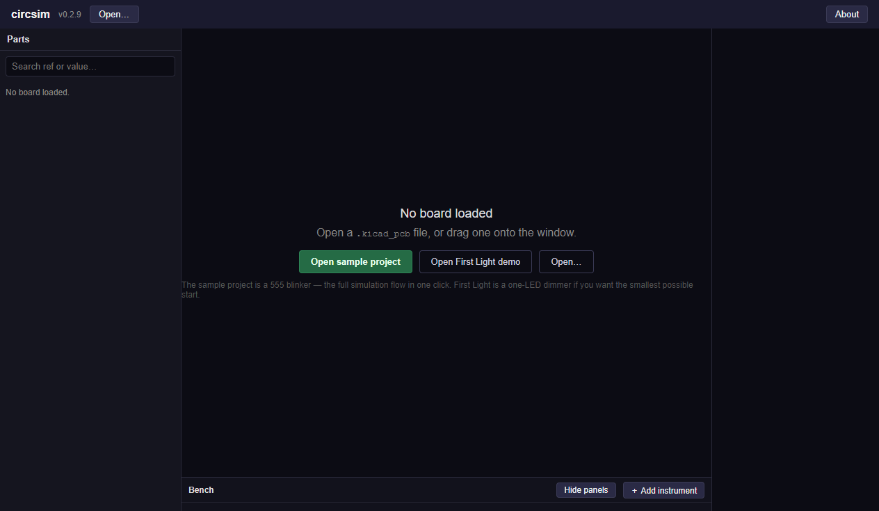
Click Open sample project. The 3D board appears, the parts list on the left fills in, and circsim quietly rebuilds the circuit from the copper.
One word you'll see everywhere: "net"
A net is everything that's electrically connected together: think of it as one "wire" of your circuit, even when it's really a branching stretch of copper. "The ground net," "probe this net," "every net gets a voltage label" all use it this way. When circsim tints the copper and labels voltages, it's labeling nets. (The sample is a 555 blinker: an astable oscillator, a circuit that flips its output on and off by itself with no input, blinking an LED.)
The lay of the land
circsim is one screen, three columns, dark by design:
- Left has the Parts list (every component, with a dot and a text label saying whether it has a model: OK, Stubbed, No model, or Open by design) and, below it, the Model Doctor (only appears when a part needs attention).
- Center has the 3D board, the bench shelf underneath it, and the scope + logs dock along the bottom. The 3D board always keeps at least 240 px of height; the shelf and the dock give way first. Each has a Hide / Show button that collapses it to a thin strip, and circsim remembers the choice between launches. If the window is smaller than about 960 by 520 px, the page scrolls instead of squeezing the board.
- Right has Ground & Power (where you designate the ground and supply nets) and the Board Critic (the read-only pre-fab audit).
Across the top is the simulation toolbar: ⚡ Energize, Power On, Run, a Pace control (0.1× / 1× / max), and an Overlay switch (Realistic / Voltage / Highlight). The Overlay changes how the copper is colored. Realistic shows the bare board (components render as simple placeholder shapes, not photo-real 3D models); Voltage tints by voltage; Highlight emphasizes your selection.
Light it up
Press ⚡ Energize.
Energize is the one-click "make it work" button. Behind the scenes it designates a ground net, clips a 5 V supply onto the board's power rail if you haven't attached one, and runs a DC operating-point solve: the steady-state voltage everywhere. Then:
- Every net gets a floating voltage label on the board.
- The copper tints by voltage (the overlay auto-switches to
Voltage). A Copper voltage scale appears at the bottom right of the board with the lowest and highest voltage printed under it; dark violet is the low end and yellow is the high end. The scale is built so it still reads for red-green color blindness: lighter always means higher. - Any LED lights up at a brightness that tracks its actual current.
That "rail at 4.98 V" readout is the reassurance moment: your board is doing something, and you can see where. (An oscillator has no steady state, so the 555's output in this frozen snapshot shows just one of its two levels, and its timing nodes sit wherever the solver parks them. The sample solves directly, with no "check these voltages" warning, because the bundled 555 model is written to be solved that way. Press Run below to watch it actually swing.)
Energize vs. Power On
Energize rigs up ground and a supply for you and solves. That's great for a board you just opened. Power On never rigs anything; it stays disabled until you've set a ground and attached a source. Use Energize to get going fast, Power On once you're driving the bench yourself.
Make it move
A DC operating point is a single frozen instant. To watch the 555 actually oscillate, press Run. circsim streams a live transient simulation: "transient" just means it computes how the voltages change over time, instead of the single frozen snapshot the operating point gives you. But you won't see a waveform until something is watching a net. So:
- Click a net on the board (say, the 555's output), then click
⌖ Probe this netin the bench header. A voltage probe clips on. - The scope (an oscilloscope: it draws voltage over time) in the bottom dock starts drawing that net's waveform in real time.
- Adjust Time/div on the scope until the square wave is nicely framed. (Time/div sets how much time each grid division represents: turn it down to zoom in on a fast signal, up to see slow ones.)
Press Pause to freeze and scrub; Run again to resume.
Stuck on a word? The dotted-underlined terms in the app show a plain definition when you hover or focus them, with a link to the matching docs page. The Docs button in the header and the Help menu open this site in your browser, and the glossary lists every term in one place.
Where to go next
- Tutorial: First Light: the full guided walkthrough on the simplest possible board: energize an LED, then dial a potentiometer and watch it dim.
- Use the bench & draw leads lets you add supplies, generators, and probes, and wire them onto the board.
- Glossary: every technical term the app uses, in plain words.
- What can circsim tell you?: read this before you trust any number. It's the honest account of the tool's limits.